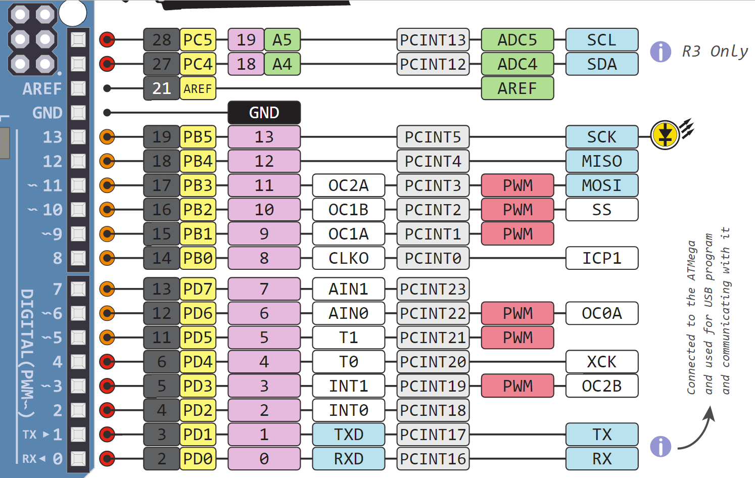

The Arduino Mega has in total one 3.3V pin and four 5V pins, which are able to provide a current up to 50 mA.Grove modules, which work on analog and digital signals, connect directly to the ATMEGA328 microcontroller on the Grove Pi. Because the Mega is the biggest Arduino microcontroller, this beast has the highest number of pins and is therefore suitable for large projects where a lot of devices have to be connected to the microcontroller. The Arduino Uno has a number of.Arduino Mega Pinout. Atmega8, 168, and 328 is identical.
The Raspberry Pi has an I2C Bus and a Serial bus. Created by Cytron Technologies Sdn Bhd All.In addition, the GrovePi enables the Raspberry Pi to access some Grove sensors directly. Please remember the port number. It sends, receives, and executes commands sent by the RaspberryPi.We bring you the Maker UNO, an Arduino UNO compatible board designed and.
Arduino Uno Pinout With Port Numbers Serial Data Line
A0 = D14In an Arduino sketch, analogRead(A0) is the same as analogRead(14).You can call grovepi.analogRead(0) or grovepi.analogRead(14)and you will get the same result.GrovePi sockets A0,A1,A2 use the AD converter and support analogRead() values 0-1023.GrovePi sockets D2-D8 are digital and support 1-bit input/output, values 0-1, using digitalRead() and digitalWrite().GrovePi sockets D3,D5,D6 also support Pulse Width Modulation (PWM) which means you can write 8-bit values 0-255 with analogWrite().Sadly you can’t use analogRead() with D3,D5,D6 and can only use it with A0,A1,A2 (aka D14,D15,D16).Grovepi.analogRead() uses the above aliases so if you are trying to read a value from an analog sensor connected to D3, analogRead(3) will actually read from the 2nd pin on the A2socket.If you analogRead(pin) where pin is 0-5, it automagically adds 14 to the pin number to read the correct digital channel, where the AD converter exists.So analogRead(2) will only read from socket A2, never socket D2.And digitalRead(2) will only read from socket D2, never socket A2.Why does the GrovePi not have any A3, A4 or A5 sockets?Channel A4 is used for SDA (serial data line) and channel A5 for SCL (serial clock line).Ok, so why was an A3 socket not added to the board?Socket A2‘s 2nd pin is A3 and an A3 Socket’s second pin would be A4.You can analogRead() A3 if you have a 4 wire analog sensor, such as some of the analog accelerometers.A4 is common with the I2C pins and would probably confuse people.Why is there no D0 and D1 sockets on the GrovePi?Because they are connected to the Serial port.On the ATmega328, D0 is for RX (receive) and D1 is for TX(transmit)TL DR grovepi.analogRead(0) - socket A0, read 0-1023Grovepi.analogRead(1) - socket A1, read 0-1023Grovepi.analogRead(2) - socket A2, read 0-1023Grovepi.analogRead(14) - socket A0, read 0-1023Grovepi.analogRead(15) - socket A1, read 0-1023Grovepi.analogRead(16) - socket A2, read 0-1023Grovepi.analogWrite(3,val) - socket D3, write PWM 0-255Grovepi.analogWrite(5,val) - socket D5, write PWM 0-255Grovepi.analogWrite(6,val) - socket D6, write PWM 0-255Grovepi.digitalRead(2) - socket D2, read 0-1Grovepi.digitalRead(3) - socket D3, read 0-1Grovepi.digitalRead(4) - socket D4, read 0-1Grovepi.digitalRead(5) - socket D5, read 0-1Grovepi.digitalRead(6) - socket D6, read 0-1Grovepi.digitalRead(7) - socket D7, read 0-1Grovepi.digitalRead(8) - socket D8, read 0-1Grovepi.digitalRead(14) - socket A0, read 0-1Grovepi.digitalRead(15) - socket A1, read 0-1Grovepi.digitalRead(16) - socket A2, read 0-1Grovepi.digitalWrite(2,val) - socket D2, write 0-1Grovepi.digitalWrite(3,val) - socket D3, write 0-1Grovepi.digitalWrite(4,val) - socket D4, write 0-1Grovepi.digitalWrite(5,val) - socket D5, write 0-1Grovepi.digitalWrite(6,val) - socket D6, write 0-1Grovepi.digitalWrite(7,val) - socket D7, write 0-1Grovepi.digitalWrite(8,val) - socket D8, write 0-1Grovepi.digitalWrite(14,val) - socket A0, write 0-1Grovepi.digitalWrite(15,val) - socket A1, write 0-1Grovepi.digitalWrite(16,val) - socket A2, write 0-1Have a question or a problem? Post it on the forums and we’ll help you out. grovepi.digitalRead(2) will read from the socket labelled D2.On an Arduino Uno (same ATmega328 chip) the digital pins are marked as D0-D13 and analog pins A0-A5.The analog pins are actually aliases for digital channels. grovepi.analogRead(2) will read from the socket labelled A2.


 0 kommentar(er)
